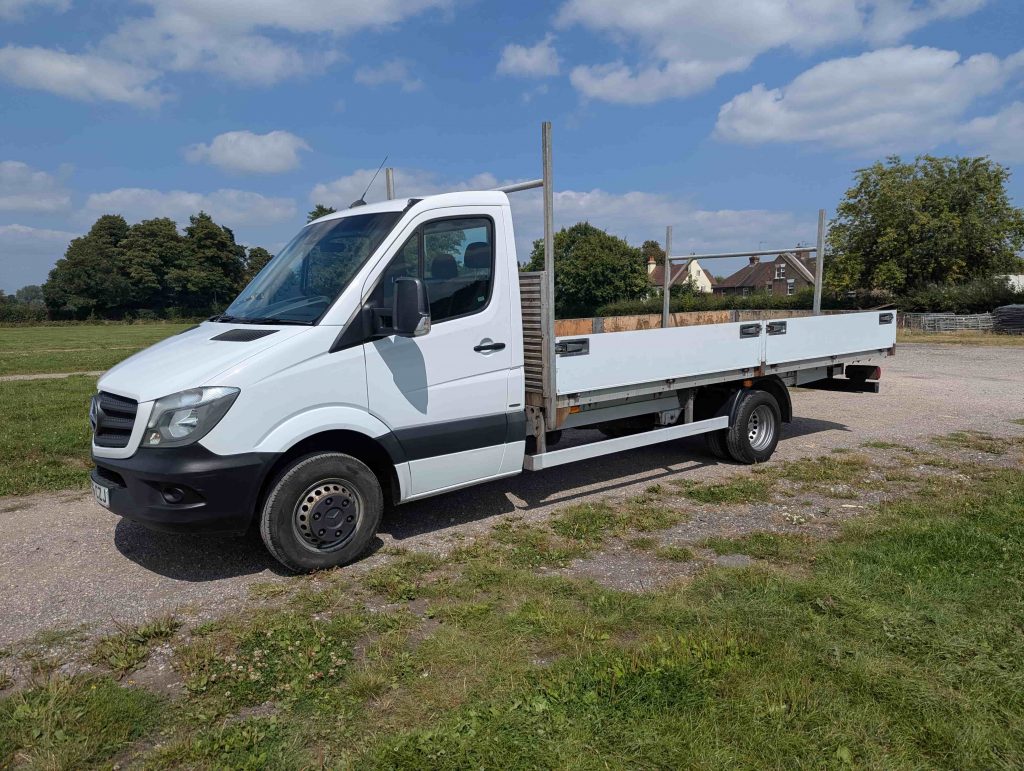
On Sunday I cleaned the van myself, with waterless cleaner and a great heap of rags, there being no water at the storage site. I scrubbed off the dust and the green algae that had crept across the body panels in the damp. The inside needed nothing. It never has. It looked, as it always has, like something just out of the showroom and never lived in.
The drive itself was a hundred and ten miles, up and round to a site near Bedford. The weather was balmy for the time of year, the low twenties and clear. I set off wondering whether I had chosen the right day, the route taking me around roughly half of the M25 (the great orbital motorway that encircles London in a single unbroken ring some hundred and seventeen miles round) from the M23 in the south up to the M1 in the north. I had not chosen well. The north-east quadrant was closed after an accident, so everything heading north had been swung clockwise, all of it piling onto the traffic already going that way. There were long stretches at a dead standstill. The first fifty-five miles, as far as just past Heathrow, took two hours. The second fifty-five, mostly motorway up the M1, took one. The ring road’s average speed is about twenty-five miles an hour against a seventy limit, so the whole hundred-and-seventeen-mile loop takes some five hours to drive round, and my morning sat squarely on that dismal figure.
Three things stood out from the crawl. The first was an aircraft. As I passed Heathrow a large jet lifted off and crossed more or less overhead, perhaps a couple of hundred metres up, the sound of it deep and thundering through the cab. A long-haul twin of that size, a 777 sort of thing rather than the very largest, leaves the ground at something in the region of two hundred and fifty to three hundred tonnes. A few hundred tonnes held aloft because the air moves a little faster over the top of the wing than beneath it. I sat in stationary traffic and thought about that for a while, the plain physics of it, which is no less of a marvel for being explicable.
The second was the road as memory. I drove this exact stretch, south to north, as a daily commute about thirty years ago, home near Gatwick to work in Kings Langley, the very same morning run I was making today. Around eighteen months of it, when I was accountant for a car sales firm. Back then they were widening the motorway from three lanes to four, and five in places. I am genuinely not sure how I managed it. We are far more resilient when we are young, and have less sense of what we are spending. There is a small irony in it, the road enlarged all those years to carry ever more traffic, and here it was today at a complete stop.
The third was the police. At two separate points on the M25, an unmarked car threaded through the stationary lanes with its blue lights going, one a BMW M3, the other a hot version of a VW Golf. Both looked exactly like the cars you would expect to belong to someone with rather grand ideas of themselves: heavily tinted, immaculate, sitting on big wheels, built to the eye for a lap of the Nürburgring rather than for police work. How convincingly disguised these things have become struck me each time, two cars I would never have looked at twice until the lights came on.
I reached the auction site, did the paperwork, took an Uber to Bedford station and the Thameslink home, about two and a half hours of trains. The auction follows next week.
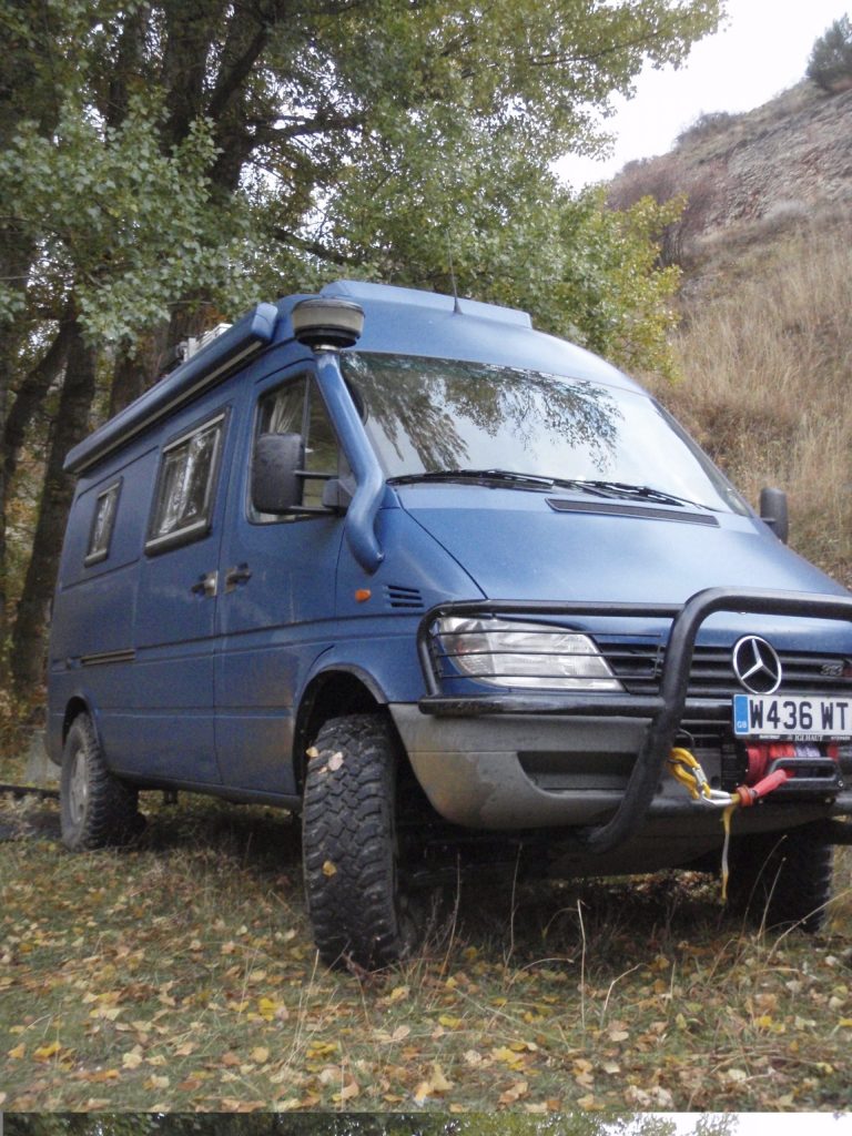
There is a symmetry to the day I cannot ignore, a van bought to cross the world yet scarcely driven before being given up, and given up along the very road I knew intimately three decades back. What is most honest to record, though, is how little I felt as I handed it over. I never bonded with it. I want to be fair: it is not a bad van. It is a genuinely good example, everything working as it should, every control precise and clean. But it always felt like just a van, and nothing ever formed between us. The contrast is with Morrison, which has real character, a more physical thing to drive, noisier, harsher, given to wallowing on its great tyres and raised suspension. You always know when you have driven Morrison. Today I drove a hundred and ten miles to part with a vehicle I had owned for two years, and felt no pang at all, and that absence is the truest thing I can set down about the day.
The mileage tells the truth more plainly than I could. A hundred and twenty-one thousand when I bought it; a hundred and twenty-two now. A thousand miles in just under three years, and a good chunk of those will be today.
I brought it home on the first of July, near enough two years ago, in the same state of excitement I had carried back from Germany. It promptly took over the driveway. It blocked the garage, made a nuisance of itself for ordinary daily use, and stood there far larger than the life around it. I measured the whole chassis end to end and built it up in CAD, and then arranged storage elsewhere simply to have our drive back.
After that I kept at the CAD in the evenings, working through the habitation box, how it might mount, how the living space would divide. The mounting was the part that weighed most. A ladder-frame truck chassis is meant to flex and twist along its length as the wheels ride over rough ground; that is not a fault, it is the design working. Bolt a rigid box straight onto a frame that moves like that and it will tear at its fixings or crack apart over a season or two. The accepted answer is a torsion-free subframe, often a three-point arrangement, which lets the chassis twist beneath the box while the box stays largely unstressed. I spent a great many evenings turning that problem over, and part of why getting it right felt so heavy was that there is no casual version of it.
And yet it never felt right. I could not have told you why. I would go back to the model, move things about, and never once arrive at the quiet certainty of that’s the one. Time passed. The van sat in the storage compound gathering dust, out of sight and, soon enough, out of mind. I had to put it through its MOT twice and have it serviced once over those years, and even those small duties were awkward. At over three and a half tonnes the thing counts as a heavy goods vehicle, so it needs a specialist MOT test station, and there are few of those, generally booked weeks ahead. Servicing was easier in principle, since any garage may service it, but at close to nine metres long very few garages would take it through their doors.
Two things slowly changed my mind, though I did not feel them as a turning at the time. At Allrad in 2025, our second visit, we went round deliberately looking at the smaller vehicles and at the Bruder off-road caravans, asking ourselves what we genuinely needed and how little space it might actually take. Then, later in 2025, we spent a fortnight in a small coach-built camper in Portugal, and we came away thinking that even that had been larger than we needed, given a bit of discipline in the planning. That was the start of the search for the new vehicle, the one we now call Morrison. The dropside, meanwhile, went on sitting unused, immaculate inside because it had never once been put to any purpose.
What finally moved it was not a fresh insight. It was the insurance and tax coming up for renewal. That administrative nudge brought the van back to mind, and I decided there and then to enter it into a commercial auction, which takes place next week.
I have been turning over what to take from all this. The honest version is unflattering. A vehicle bought to cross the world covered about a thousand miles in two years, sat in a compound, and quietly cost me specialist test bookings, the hunt for a garage long enough, and tax and insurance ticking over month after month for a thing I never saw. The deeper lesson is the one about being out of sight. Once it was stored away the problem stopped nagging at me, but it did not go away; it simply persisted, unsolved, for years. The right order of priorities would have had me face the thing that plainly was not working, rather than let distance and inertia decide it for me. I named the conflict only in hindsight, that pull between a big box built for developed-world comfort and a wish to go light and far, and even now I hold the naming of it loosely.
The van (not Morrison) went off to auction today, and the drive up gave me the better part of three hours to think about how I came to own it at all. So I will set the beginning down first, while the whole shape of the thing is in my head.
It began, properly, more than two years before I ever bought a vehicle. There was a plan, an overland tour that would take us right across the world, and for a long time it lived only as reading, calculation and argument with myself and then discussed with Ochi. Then in 2024 we went for the first time to Abenteuer & Allrad at Bad Kissingen, the great off-road and expedition gathering, around two hundred and fifty exhibitors spread across the ground with everything from roof tents and cookers to vehicles the size of small houses. We gave it two and a half days. We climbed inside as many builds as would let us, talked to the people who make them, and learned more in those few days than in the previous year of reading.
The spread of what was there has stayed with me. At the modest end, Toyota pickups carrying a compact living box on the back, or Ineos Grenadiers fitted out with storage, a few pull-out fittings and a roof tent. At the other, six-wheeled all-wheel-drive monsters with four-wheel steering, twenty tonnes and more, and a handful of eight-wheeled things that looked built to cross a continent without noticing it was there. Walking between the two extremes did most of our deciding for us.
I came home full of it and went straight to the classifieds. Within a short while I had found what looked ideal: a one-owner 2016 Sprinter 516 dropside, extra-long wheelbase, full service history, a hundred and twenty-one thousand miles on it. I bought it.
The design brief in my head was by then quite firm. We did not want one of the fifteen-tonne-plus luxury expedition trucks. They are magnificent, but we wanted to take narrow mountain passes as well as open country, and I wanted to be able to mend the thing myself in a field if it came to that. Changing a wheel on one of the giants means wrestling something close to or over a hundred kilograms; a single military-pattern tyre, a 395/85 R20, is around ninety-five to a hundred kilograms before you even add the rim. That just did not seem like any fun at the roadside in the middle of nowhere. So I set a ceiling of seven and a half tonnes and meant to stay under it.
Against that, we wanted the comforts of home, and comfort costs both volume and weight. I had a target habitation box of roughly five and a half metres by two point two by two point two, divided properly into kitchen, shower room, bedroom and living room, with a garage at the back for bicycles, spares and tools. A washing machine. Air conditioning. Working from those, I reckoned on at least two hundred and fifty litres of water, the washing machine being a thirsty thing, and around fifteen kilowatt-hours of stored energy. The box itself I meant to build in composite throughout, carbon fibre and glass fibre according to where each belonged, and bring in at about two to two and a half tonnes.
The dropside made sense for a reason that seemed obvious once I had it. A dropside body is the easiest of all to strip away, leaving the chassis clean and exposed for a separate habitation box to be mounted on it. The extra-long wheelbase I chose simply because, at the time, I thought we needed a large box to live in.
On paper it was coherent. I had thought it through honestly and the numbers held together. Sitting here now, I can see the seed of the later trouble sitting quietly inside that coherence: a big box, sized for living the way one lives in a comfortable house, set against a wish to travel light and travel far. I did not see it then. I see it now, though I am not yet sure I have fully made my peace with it.
When I left you last, the new transducer was in, everything was reconnected, and I was standing over the engine bay with rather less optimism than the first time and rather more dread. I started him, let him settle, gave the throttle a push, and listened.
Nothing. Again.
No whistle, no whoosh, the revs rising in that same flat, lifeless line. After the wiring, after the sensors, after the transducer, here we were once more, near enough where we had started, with a turbo that turned the fuel into noise and motion and no useful boost whatsoever. I will not pretend I took it well.
A flicker of something
Out came the phone again, propped against the slam panel with the camera trained on the turbo, engine running, throttle blipped, footage reviewed on the bench afterwards with a coffee going cold beside me.
And this time, movement. The actuator lever swung open as the revs climbed and drew back as I lifted off, smooth and willing, doing precisely what a healthy turbo asks of it. The new transducer was passing vacuum properly. The actuator was answering it. The whole long chain I had spent two posts chasing, brain to valve to vacuum to rod to lever, was finally doing its job from one end to the other.
Which was wonderful, and also rather sobering, because it left exactly one suspect standing.
If the command was good, and the vacuum was good, and the lever was moving as it should, and the turbo still wasn’t making boost, then the fault had to lie past the lever, inside the turbo itself. And I already knew a good deal about the inside of this turbo. Back in the first post I had it on the bench and checked the heart of it: the turbine, the shaft and the compressor wheel, all sound, no play, no scoring, no wobble. The spinning parts were fine.
That left only one thing. The vanes. You’ll remember them: the ring of little movable fins inside the exhaust housing that aim the gas at the turbine and decide how hard it spins. The lever was moving. So either the vanes weren’t moving with it, or they weren’t moving at all. Either way the answer was the same, and it was not the answer I wanted.
The turbo had to come off again.
Off it comes
I’ll spare you the full liturgy of disassembly, since you sat through it once already and the steps don’t improve with retelling. The cluster of innocent components around the exhaust side, off. The connections in their order. The exhaust bolts, properly torqued this time and so a fair bit more stubborn than the loose ones I’d found at the start of all this. The mount. And the turbo on the bench, looking smug.
The turbo out and on the bench. The bronze, rust-darkened casting on the right is the exhaust housing, where the vanes live, bolted on around its rim. Getting the bolts out was the easy part.
Have a look at that picture. The bronzy, rust-coloured section on the right is the exhaust housing, and it’s bolted on radially, all the way round its edge. That’s the part the exhaust gas enters, and it’s where the vanes sit. To get at them, that housing had to come away from the rest of the turbo.
The bolts, as I say, came out without much fuss. The housing itself was another matter entirely. Years of heat and exhaust grime had welded the two castings together far more effectively than any bolt ever could, and what should have been a simple parting of two faces became a long argument conducted with a mallet. I tapped, then I hit, then I hit it harder, working round and round the joint, and it gave not a millimetre. My hands took most of the punishment, knuckles grazed on this casting and that bracket, and my temper took the rest. It came off in the end, suddenly, the way these things always do, with a crack and a shower of carbon and very nearly my own knuckles into the workbench.
The thing that was actually broken
And here I have to apologise, because I didn’t take a photograph, and I’ve regretted it ever since, because what was inside was genuinely fascinating to look at.
The mechanism that drives the vanes is a clever piece of geometry. The lever on the outside, the one I’d watched moving so happily on the video, turns a flat disc inside the housing. Around the edge of that disc sits a ring of small cams, one for each vane, and as the disc rotates it nudges every cam, and every cam swings its vane, all of them moving together by the same amount in the same instant. One lever, one disc, a dozen vanes turning as one. It’s the sort of thing you could watch all afternoon.
When it works. Mine didn’t. The little cam that takes the motion from the lever and feeds it into the disc, the very first link in that chain, had snapped clean. So the lever turned, exactly as the video showed, and turned, and the disc behind it sat there doing nothing at all. The whole graceful arrangement of disc and cams and vanes was sitting idle behind a lever that thought it was hard at work.
There was my missing boost, finally, at the very bottom of the well. And there too was nothing I could do about it. A broken internal cam in a sealed turbo is not a repair, or at least not one I’m equipped to make at the kitchen-table end of a driveway. The turbo was finished.
Remanufactured, not new
Which brought me to the till, and an unpleasant moment with it. A brand-new turbo for Morrison, where one can even be found, costs the sort of money that makes you sit down. Remanufactured is the sensible road: you send your old unit in as an exchange, a workshop with the right tooling strips it, replaces what’s worn, and sends one back rebuilt to spec for a fraction of the price of new. So that’s what I did. Box up the old one, send it off, and wait.
A week, near enough, which is by now the standard unit of time in this whole saga. While I waited I ordered a full gasket kit to put it all back together with, and a second kit on top of that to live in the van as a spare. If this restoration has taught me anything, it’s that the part you need is the one you don’t have, a thousand miles from the nearest counter. Better it rides along.
The remanufactured turbo arrived. New gaskets in, every joint fresh, and the whole reverse procession went back together: the mount, the exhaust, the oil feed and drain, the charged-air pipe, the air feed, and the cluster of innocents bolted back over the top, each fixing checked to its proper torque.
The remanufactured turbo back in its place, plumbed in and torqued down. The last piece, I hoped, of a very long puzzle.
The moment I’d been waiting three posts for
And then there was nothing left to do but start him.
I turned the key. He caught at once and settled to idle, and I made myself leave him there. No revs, no testing, not yet. I let him idle and warm, watching the temperature needle lift off its stop and begin its slow crawl upward, the oil thinning and circulating, everything coming up to heat the way it should before I asked a single thing of it. It was the longest few minutes of the entire job. I’d been disappointed at this exact moment twice before, stood in this exact spot with my hand near the throttle, and twice it had given me nothing.
Needle up. Oil warm. I gave it some revs.
The revs gathered, quickened, and just shy of 1,800 rpm they took hold and surged, and over the top of them came a sound I’d been chasing since the very first post: a clean, rising whistle, the turbo spooling up and piling the air in at last. I lifted off, and there it was, the soft whoosh of the dump as the pressure let go.
I may have made a noise myself, standing there in the cold. I’m not going to tell you what it was.
Drawing the thread back
We had it. The whole turbo circuit, end to end, finally understood and finally working. And it’s worth stepping back to count what that took, because almost nothing came back fixed the way it went in. The actuator, reset off its welded position. The boost-pressure and air-temperature sensors, both renewed. The transducer, replaced. And now the turbo itself, the very part I’d cleared as healthy in the first post, condemned at last by a single broken cam the size of a fingernail. Most of the circuit, in the end. Very nearly the lot of it.
I’ll resist the urge to point a finger at whoever came before me. The welded actuator I found in the first post, the reworked wiring in the second, the broken cam in this one, I think these are mostly just the marks of age and hard miles. Morrison is twenty-five years old and has crossed the Sahara twice. Things wear, things tire, and a vehicle this old is really only the sum of every repair that has kept it on the road this long. Whoever set that actuator and ran that wire was, I suspect, doing their best with whatever was failing under them at the time, exactly as I have been these past weeks.
What I had, that they perhaps didn’t, was the time, the stubbornness, and a blog to answer to. There was never a shortcut here, only the long way round, one ruled-out suspect at a time, all the way down to a broken cam I omitted to photograph. Three posts, the better part of six weeks of waiting on parts and puzzling over multimeters, and something like five days of actual work scattered across them. For a part the size of your fist, that is a great deal of fuss, which is more or less where the turbo page came in, all that time ago.
But Morrison whistles now, and whooshes when he’s done. After all of it, that small noise is the sweetest thing I’ve heard in months.
When we left off last time, the turbo was back in, every fixing checked and checked again, and I was standing over the engine bay with that particular mix of optimism and quiet dread that comes just before you turn the key. So I turned it.
Morrison started without complaint. I left him ticking over for a few minutes, idling gently, partly to let everything warm through and partly to be sure the oil and the other fluids were circulating properly before I asked anything of him. So far, so good.
Then the first test. I gave the throttle a gentle push, expecting the revs to gather quickly from around 1,800 rpm (the point where a turbo like Morrison’s typically starts piling on the forced induction in earnest), and expecting, too, to hear something of the turbo’s character: a faint whistle as it spooled up, perhaps a soft whoosh as I lifted off. Instead, nothing. The revs climbed in a straight, flat line, the way a tired engine with no turbo at all would, and not a single turbo-ish noise to be heard. Odd.
Ruling things out
Working alone, with nobody to watch the engine while I worked the throttle, I pressed my phone into service as a second pair of eyes. I propped it up with the camera pointed squarely at the turbo, started the engine, blipped the throttle, shut it down, and reviewed the footage. The actuator, the vacuum-driven unit that swings the vanes and the very part I’d spent the last post adjusting, hadn’t moved at all. Not a flicker.
So began the process of elimination.
Had I simply forgotten to reconnect the vacuum hose? It would not have been the most embarrassing thing I’d ever done, but the engine bay is a tight place and stranger things have slipped my mind. I went underneath and looked. The hose was there, connected, seated properly.
Was it blocked, then? I pulled the hose off at both ends, the actuator and the transducer, and blew through it. Clear as anything, no obstruction.
Had I damaged the actuator itself when I wrestled the turbo back into place? I pushed the vane control arm by hand. It moved through its travel with a firm, reassuring stiffness, exactly as it should. Nothing wrong there either.
Each suspect, questioned and released. Which left one obvious candidate: the transducer, the little electronic valve that meters the vacuum to the actuator on the engine’s orders.
Getting at the transducer
Reaching the transducer is not, it turns out, a five-minute job. To get to it I first had to remove the airbox, and then the headlight, and the headlight in turn was blocked by the light guard, the protective metal cage that sits over the lamp on the bull bar.
A word on the bull bar, for anyone who hasn’t met one. It’s the sturdy steel frame across the front of the van, the sort you’ll see on vehicles built for remote or rough country. Its job is to protect the front of the vehicle, the radiator, the lights and the vital bits behind them, from the things you might meet a long way from a workshop: an animal in the road, a low branch, a rock thrown up off a bad track. The light guards are part of the same idea, little cages bolted over the lamps to stop a flying stone from putting a headlight out. Excellent when you’re in the middle of nowhere, and mildly infuriating when all you want to do is get a headlight out on your own driveway.
So: light guard off, headlight out, airbox out. And there, finally exposed, was the transducer, and a surprise sitting alongside it.
A previous mechanic’s handiwork
The wires running to the transducer were not standard. The original wiring had been cut away, and a length of non-standard wire spliced in to take its place. I traced this replacement wire back to see where it went, and it led me all the way to the ECU.
A quick word on the ECU, since it’s about to become the centre of the story. ECU stands for Engine Control Unit, and it is the engine’s computer, the brain I described last time as sitting at the head of the chain: brain, to valve, to vacuum, to rod, to fins. It’s a sealed box of electronics that reads a host of sensors and decides, many times a second, exactly how the engine should behave, including how much boost the turbo ought to be making and therefore what to tell the transducer.
The ECU itself, out and in hand. Morrison’s brain. Everything the engine does begins here. Note the rows of multi-pin connectors along the top, each wire landing on its own numbered terminal.
I followed the replacement wires to the ECU, and right there beside them I found the cut ends of the two original wires, snipped off and abandoned. Someone, at some point in Morrison’s past, had bypassed the factory wiring and run their own.
That raised an immediate and rather worrying question. Had whoever did this actually connected the replacement wires correctly? Wires don’t simply bolt onto a computer; they terminate in a connector, a plug, and within that plug each wire sits in its own numbered slot so that it lands on the correct terminal of the ECU. Getting a wire seated in the right slot is called pinning it. Pin a wire into the wrong cavity and it will sit there looking perfectly connected while its signal goes nowhere useful at all. So: were these wires pinned to the right pins?
The repinned connector in hand, the spliced-in replacement wires clearly visible (blue and brown). The factory wires were cut and these run in their place, all the way back to the ECU.
Turning the problem round
How on earth do you check that, with no documentation to hand? I scoured the internet for a technical wiring diagram for the ECU, the kind that would tell me which pin ought to carry which signal. I came up empty, even among the diagrams you can usually buy for a not-unreasonable fee. Nothing.
So I turned the problem round. Rather than prove the wiring correct from the diagram inward, I would measure what was actually arriving at the far end and work backward. If the right signal was reaching the transducer, then the wires had to be connected to the right pins and sound along their whole length. The proof would be in the signal.
Here I need to explain what kind of signal we’re looking for, because it isn’t quite what you might picture. The ECU doesn’t control the transducer with a smoothly varying voltage. It uses something called PWM, or pulse-width modulation. Rather than dimming the supply up and down like a household dimmer switch, the ECU switches the full voltage fully on and fully off, very rapidly, many times a second, and varies the proportion of time it spends switched on. That proportion is the duty cycle. Fifty per cent duty cycle is on half the time; seventy-five per cent is on three-quarters of the time. A solenoid, and a multimeter, both respond to the average, so a signal that’s on 75% of the time reads as roughly 75% of the supply voltage. It’s a tidy way to control something precisely using nothing more than a fast on/off switch.
One more thing to hold in mind before the numbers: the voltage in a vehicle is not a fixed quantity. We talk loosely about a “12-volt” system, and a battery sitting at rest does read somewhere around 12.6 volts. But the moment the engine starts, the alternator wakes up and begins charging the battery, and to push charge back in it has to work at a higher pressure, typically around 14.4 volts. So the supply voltage in the van climbs from roughly 12 volts with the ignition on and the engine off, up to around 14.4 volts with the engine running and the alternator at full output. This matters, as you’ll see.
I stripped down the plug that connects to the transducer, put my multimeter across it, set the phone recording once again, and ran the engine. Here is what the video gave me.
With the ignition off, the reading sat at zero. Turn the ignition on, engine still off, and it jumped to about 9 volts. As I cranked and the engine caught, it dipped to 5.5 (the starter and everything else hauling hard on the battery for a moment), then climbed quickly back to 9.5 as it settled into idle, and crept on up to 10.5 over the next five seconds or so as the alternator got into its stride. I revved it to 3,000 rpm and it nudged up a touch more, to 10.83. Then I switched off, and it fell to 9.26 before dropping away to zero.
At first glance those wandering numbers look like the ECU busily doing its job, varying the signal as the engine’s state changes. But watch what happens when you measure each one against the supply voltage at that exact moment:
Ignition on, engine off: 9 volts against a roughly 12-volt battery is 75%. Idle just after starting, battery recovering: 9.5 against about 12.7 is 75%. Idle after five seconds, alternator charging properly: 10.5 against about 14.0 is 75%. At 3,000 rpm, alternator at full chat: 10.83 against about 14.4 is 75%. Engine just switched off, a little surface charge left on the battery: 9.26 against about 12.3 is 75%.
Every single reading comes out at almost exactly 75%. The numbers had nothing to do with the ECU modulating the turbo. They wandered only because the supply voltage beneath them was wandering, and the signal rode passively along on top of it. The duty cycle, the actual command from the ECU, never budged from 75%. Rock steady.
Two things at once
Now, that steady 75% told me two things, and the second one took a moment to sink in.
The first was the answer I’d gone looking for: a clean, coherent PWM signal was reaching the transducer, and that could only be true if the replacement wires were pinned to the correct terminals at the ECU and were sound from end to end. The previous mechanic’s handiwork, whatever else might be said about it, was electrically fine. The wiring came off the suspect list.
But the second thing was the more interesting, and I’d very nearly walked straight past it. A fixed 75% duty cycle that never moves, no matter what the engine is doing, is not what a healthy ECU produces. A healthy ECU is forever adjusting, nudging the figure up and down as the revs and the load change, chasing the boost it wants moment to moment. A flat, unchanging number is a tell-tale. It’s what an ECU falls back to when it has given up.
Engine computers are built to be cautious. When one detects that something it relies upon has stopped making sense, a sensor reading that’s drifted out of range, or a result that doesn’t add up, it doesn’t keep trying to do clever calculations on bad information. It abandons proper closed-loop control and retreats to a safe, fixed default, a sort of mechanical shrug. You’ll often hear this called limp mode. In effect the ECU was saying: I can’t work out what the turbo should be doing, so I’ll just hold this one safe value and leave it there. That value was 75%, and it would never move while the fault persisted.
So the transducer wasn’t necessarily broken at all. It might simply have been faithfully obeying a stuck command. Before I could blame it, I had to find out why the ECU had downed tools in the first place, and that meant looking at the sensors feeding it.
The sensor the ECU had lost faith in
The most likely culprit was the boost pressure sensor. This is a small sensor that measures the pressure of the air on its way into the engine, the very thing the turbo exists to raise. It sits between the intercooler and the intake manifold (which is the shared gallery that takes the incoming air and distributes it evenly to each of the cylinders; it’s the last stop for the air before it enters the engine.) That sensor is precisely how the ECU knows whether the turbo is actually delivering. If its reading goes sour, the ECU is suddenly blind to the one measurement it most needs, and limp mode is exactly the sort of response you’d expect.
Sitting right beside it was an air temperature sensor, which tells the ECU how hot that incoming air is (and therefore, as we covered on the turbo page, how much oxygen it really contains). Two sensors, side by side, both feeding the same decision. Rather than test each in isolation and risk replacing one only to find the other at fault, I decided to renew them both together. I ordered them up, waited the by-now-customary week for them to arrive, and fitted them.
Then I ran the same test again, multimeter on the transducer plug, phone recording. And this time the picture was quite different. As I worked the throttle, the duty cycle came alive, swinging across the full range from 0 to 100% as the revs rose and fell, exactly the restless, adjusting behaviour of an ECU doing its job properly. The computer had its sight back. Replacing those sensors had cleared whatever fault had blinded it.
But, and there’s always a but in this story, it didn’t last. After a few seconds of proper control the duty cycle gave up and settled back to that same flat 75%. The ECU would start out trying, then quietly retreat to limp mode all over again.
That actually made perfect sense once I thought it through. The ECU now had good sensors and was willing to command boost. But it commands boost and then watches the boost sensor to see it arrive. If it asks for boost and nothing happens, no rise in pressure, no response at all, then as far as the ECU is concerned something downstream is still broken, and back to the safe default it goes. The sensors had been one fault. There was clearly another, further down the chain.
Back to the transducer after all
So now, with the wiring cleared and the sensors replaced, I came back round to the transducer with a much better idea of what I was testing. I connected my vacuum tester to the output of the transducer, the side that feeds the actuator, set the phone recording, and ran the engine.
Nothing. No vacuum at all.
This needs a small clarification, because the transducer doesn’t actually make vacuum. It’s only a valve. The vacuum itself is generated by a pump on the engine and held in a small reservoir nearby, ready to be drawn upon, and the transducer’s job is simply to meter out as much of that stored vacuum as the ECU asks for. So no vacuum at the transducer’s output could mean a faulty transducer, or it could mean there was no vacuum arriving at its input to begin with.
So I ran the same test one step further back, on the output of the reservoir. This time the gauge showed a brisk build-up of vacuum from the moment the engine started, climbing to around 700 mmHg and holding there. The supply was perfect, plenty of vacuum, exactly where it should be. For good measure I checked the short length of pipe between the reservoir and the transducer, and that was sound too.
Which left only one possible conclusion. Good vacuum was arriving at the transducer. A live, willing PWM signal was arriving at the transducer. And still nothing came out the other side. After all the rerouting and ruling-out, the thing I’d suspected at the very start turned out to be guilty after all. The transducer was also broken.
A new part, and a held breath
I ordered a replacement. A week later it arrived. I fitted it, reconnected everything, and, with rather less optimism and rather more dread than the first time around, started the engine, gave it some revs, and…
If you’ve been following along, you’ll remember that back in the maiden voyage post I mentioned, almost in passing, that the turbo needed some attention. I left it there at the time, a loose thread to be picked up later. Well, later has arrived, and as it turns out that loose thread unravelled into something rather larger than I’d bargained for.
Before I go further: if you’ve never been entirely sure what a turbocharger actually is, or why a part the size of your fist can cause this much trouble and fascination in equal measure, I’ve written a separate page explaining the whole thing from first principles. It’s genuinely one of the most elegant pieces of engineering on the van. It makes power out of the engine’s own waste, and the rest of this story makes far more sense if you’ve read it. You’ll find it here: [The Turbo]. Go on, have a look. I’ll wait.
The two symptoms
The trouble announced itself in two ways.
The first I’d felt for most of the long drive home: the power was simply lacking. Not dramatically, not a breakdown-on-the-hard-shoulder sort of problem, but a persistent sense that Morrison was working harder than he should to do less than he ought. On the flat you’d not notice. On a long climb, fully loaded, you noticed.
The second was harder to ignore, and it arrived once we were home: a rattle. A distinct, mechanical rattle coming from somewhere in the vicinity of the turbo. Now, a rattle near a part that spins faster than anything else on the vehicle, floating on a thin film of oil, is the kind of sound that gets your full attention rather quickly. My mind went straight to the worst case: something loose, something failing, metal somewhere it shouldn’t be. There was nothing for it but to take the turbo off and have a proper look.
Getting the thing out
This is where the fun started, and I use the word “fun” in the way only someone who has since recovered from the experience can.
Two of the bolts holding the turbo in place were, to put it generously, thoughtfully positioned, which is to say almost impossible to reach. Getting to them meant first removing a whole cluster of other components around the exhaust side of the engine, none of which had anything wrong with them and all of which simply happened to be in the way. So off they came.
Then remove all the turbo connections in the usual order: the air feed, the charged-air pipe, the oil feed and the oil drain. Then next the turbo’s exhaust outlet had to be disconnected, and that meant going underneath the van to loosen the bolts securing the exhaust itself. And here I found something odd: those bolts were loose already. Properly loose. I noted them as a job to put right on reassembly, and carried on.
Finally, with the exhaust freed, it was a simple matter of removing the turbo mount. And with that, hey presto, the turbo was out and on the bench.
The good news, and the real mystery
The first inspection was reassuring. The turbine, the compressor wheel and the shaft joining them were all in good order. No damage to the blades, no scoring, and crucially no untoward movement in the shaft, no play or wobble that would have spelled worn bearings. The heart of the turbo was healthy.
And that is when the penny finally dropped about the rattle. If the turbo’s insides were sound, then the noise had never been coming from the turbo at all. It was those loose exhaust bolts, the exhaust knocking about because its fixings had worked their way loose, throwing a sound up into the engine bay that, for all the world, had seemed to be coming from the turbo. One of my two problems, solved almost by accident, and nowhere near where I’d been looking.
So if the spinning parts were fine, why the missing power? For that, I had to look at the part of the turbo that controls it.
The clever bit: how a turbo knows when to work
The separate page touches on this, but it’s worth spelling out here, because it’s central to the whole story.
A turbo doesn’t want to be making full boost all the time. At low engine speeds there’s barely any exhaust to drive it, and the moment a driver lifts off the throttle you want it to stop forcing air in, and stop quickly. So a modern turbo like Morrison’s is a cleverer thing than a simple fixed device: it adjusts itself, moment to moment, while the engine runs.
The way it manages this is rather beautiful. Inside the exhaust housing, ringed around the turbine, sits a set of small movable fins, or vanes. By changing their angle, the turbo changes how the exhaust gas is aimed at the turbine. Close the fins down and the gas is funnelled through narrow gaps, speeding up and hitting the turbine hard, giving lots of boost even at low engine speed. Open them up and the gas flows past gently, giving little boost but instant response when you back off. It’s the same trick as putting your thumb over the end of a hose to make the water shoot further.
Something has to move those fins, and that something is the actuator, the black unit you can see mounted on the middle of the turbo. The actuator, in turn, doesn’t run on electricity or oil pressure but on vacuum: gentle suction, drawn from the engine, that pulls a diaphragm inside the actuator and moves a rod connected to the fins. The more vacuum applied, the further the rod travels and the more the fins move.
Of course, vacuum on its own is just vacuum, and it needs to be metered out precisely. That’s the job of a small electronic valve called a transducer (you may also see it called a boost-pressure solenoid or an electro-pneumatic converter, same idea). The engine’s computer tells the transducer how much vacuum to pass through to the actuator at any given instant, and so, indirectly, the computer commands the fins. Brain, to valve, to vacuum, to rod, to fins. That’s the chain.
Where it had all gone wrong
Now to the interesting part.
That actuator is supposed to begin moving the rod at a fairly modest vacuum, somewhere around 150 mmHg, and to reach the end of its travel by around 420 mmHg. That’s the window the engine’s computer is designed to work within, and I’d tracked down a technical document for the actuator that confirmed those figures.
But when I tested Morrison’s, the actuator wasn’t starting to move until around 400 mmHg, and wasn’t reaching full travel until something like 700. In other words, the whole operating window had been shifted far out of reach. The vanes weren’t even beginning to close until the vacuum was already up where they should have been very nearly fully deployed. The computer was asking for boost in its normal range, and the actuator was effectively shrugging and saying not yet, not yet, never moving the fins enough to spin the turbo up properly. The turbo was barely engaging at all.
And there it was. The missing power, explained. Morrison hadn’t been ill so much as half-asleep.
The fix, mercifully, was simple in principle: the actuator rod has a threaded adjuster, and by threading it in I could bring the start of its travel back to the correct pressure. I set it so movement began low, back around that 150 mmHg mark, with full travel arriving in the low 400s, right in line with the document. One small, oddly satisfying detail: there was a blob of weld sitting right at the point I eventually adjusted it to. Someone, at some time, had deliberately set this actuator and fixed it in place. I’ll let you draw your own conclusions about that for now; it’s a thread I’ll come back to.
Buttoning it back up
With the actuator set correctly, it was time to reassemble, and that meant new gaskets.
A gasket is simply a thin layer of material that sits in the joint between two metal parts and seals it. Metal surfaces are never perfectly flat, and the gaps between them, however tiny, are more than enough for hot exhaust gas or oil under pressure to escape through. The gasket is squeezed between the two faces and deforms to fill every imperfection, making the joint properly gas- and oil-tight. They’re not reusable, either: once a gasket has been crushed into shape and cooked by exhaust heat, it’s done its job and won’t seal a second time. So every joint I’d opened got a fresh one.
New gaskets in, the turbo went back on: the mount, the exhaust reconnected (and those loose bolts properly torqued this time) the oil drain and feed, the charged-air pipe, the air feed, and finally all the bits and pieces I’d had to strip away to reach the wretched thing in the first place and then check all the fixings are tightened to the correct torque. And away we go.
So, problem solved, full power restored, lesson learned?
Well. That was certainly what I thought as I stood back and admired the job. It was also, as it turned out, only the very beginning. Because the actuator was just the first of the things I was about to discover wrong with Morrison’s turbo circuit.
The last morning at Kunzmann’s. We had done most of the packing the night before, so there was nothing to do but go down to breakfast at eight and eat slowly, which is a luxury I do not often allow myself on the final day of anything. The dining room had the settled quiet of a place where most of the guests have already left or are about to. Dry light at the windows; the promise of a clear run.
The useful thing happened over the rolls and coffee, which is generally where useful things happen. A man at a nearby table turned out to be staying at the hotel and working a stall at the show, one of the stalls Ochi and I had walked past without stopping. He was with Separ, who make filters for diesel, the marine and industrial and automotive sort that strip particles and water out of fuel before it reaches the engine. Water in the tank is the kind of small, stupid hazard that can finish an engine in a place where there is no help for a thousand miles, and so the conversation took hold at once. His stall had been linked to Bimobil, whom we had deliberately not sought out, since Bimobil build whole vehicles and we are building our own. Filters, though, are exactly our concern. We swapped details. He offered to talk it through properly once we were home, and I mean to take him up on it.
What he said dovetailed with a plan for the Sprinter that I have been turning over for months. The idea, borrowed straight from boats, is two tanks: a large one for storage and a small day tank that the engine alone draws from. Each morning you pump from storage to the day tank, passing the fuel through the filter on the way, so that whatever the engine sees has already been cleaned of water and grit. It is the sort of arrangement that costs a little in plumbing and complication and pays for itself the first time you fill up at some remote pump with fuel of doubtful provenance. To have a name and a firm and a willing contact arrive by accident on the last morning, after three days of looking for exactly this kind of thing on purpose, was a quiet pleasure.
We left at half past nine. Five hundred and fifty miles ahead, the SL with its soft top up as it had been the whole trip, the 1997 car carrying us home as steadily as it had carried us out. I had loaded a long playlist days ago, rock and jazz and classical with a little funk threaded through it, and we simply let it run, as we had let it run across the whole journey.
Three stops, to mirror the outbound leg, which had also taken three. The first was fuel: Shell V-Power Racing, the 100RON grade, at 2.80 euros a litre. Dearer even than the fill on the way out, which had been close to 2.50 at a middle stop. I have only ever found that grade in Germany, and so I bought it as a kind of send-off for the old car, a last treat before the duller petrol of home, the price be damned. The second stop was for legs and food, the rolls we had made up at breakfast and wrapped in a napkin, eaten standing by the car. The third, more fuel, at the Belgian and French border.
It was at that second stop that the roof finally came down. The sky had settled into a clean, washed blue and the air had turned properly warm at last, and there seemed no longer any reason to keep the world shut out. Down it went, for the first time all week, and it stayed down the rest of the way into Calais. I had half expected it to be worth having only on the country roads, but it was the opposite: with the top folded away even the plain motorway miles changed character entirely, the noise and the rush of air no longer something to be sealed against but the whole point of the thing, the drive turned from a distance to be covered into something to be in. Nine hundred miles of this trip with the roof up, and the best of the driving came in the last few hours with it down.
The traffic flowed the whole way, which on a return leg through Germany, Belgium and France is not to be assumed. We reached the LeShuttle terminal at Calais at quarter to six, a full hour and a half ahead of check in closure for the train we had booked, and were waved onto an earlier train. Home by half past eight, local time.
Twelve hours, door to door. The same as the journey out, to the hour. There is a tidiness to that which I noticed with more satisfaction than the fact really warrants. Between songs, and again on the last stretch of motorway, Ochi and I came back more than once to the same observation: that it had been a genuinely restful trip and a productive one, which is a rarer combination than it sounds. The Separ conversation is the loose end I want to pull on first. Filters, two tanks, a morning routine of pumping clean fuel forward. A year from now it may be the thing that keeps us moving.
The showers came and went all morning, never quite settling into rain proper but never clearing either, and by the time we had finished breakfast it was plain the walk up to Botenlauben was off. We had planned the climb through the woods to the castle, but the sky had other ideas, and I felt no particular loss in it. We have made that walk before, on drier days, and there is a comfort in knowing a place well enough to let the weather decide. So the day became a slow one by agreement, which suited us both.
We drove into Bad Kissingen and took lunch at one of the town’s bistros. I will not name it, partly because there are several and partly because the one worth recommending one year may have changed hands the next, so the name would only mislead anyone reading this later. The food was unfussy and good, and we sat over it a long while. The talk turned, as it has each evening this week, to the van. We are at the stage of reckoning with how much work is still ahead, which jobs we cannot do ourselves and will need to bring specialists in for, and how to keep the budget from running away, as it so easily does. I will set all that down properly another time, when the decisions are made rather than half-made. For now it is enough to record that the conversation widened rather than narrowed.
For those who follow, and we have now spent parts of three years coming back to this town, I want to put down what is worth seeing here while it is fresh enough to be useful.
Bad Kissingen lies in a valley on the Fränkische Saale, the Franconian Saale, which runs roughly north to south through the middle of it. That single fact shapes nearly everything. Because the town sits low, almost any walk out from the centre means climbing, and some of it climbs steeply. Around the spa quarter, though, the ground is gentle and given over to gardens and parkland, the Kurpark, the Altenberg, the Luitpoldpark and the Rose Garden, a dense green fabric laid out along both banks. The parkland spans the river, and throughout it deck chairs are set out for anyone to use, so that you can take your own patch of shade or sun and simply sit. I have always liked that. It asks nothing of you.
There is a scented path through the parkland, perhaps two hundred metres of it, that I think of separately from everything else. The roses there are not the formal kind in disciplined beds; they grow looser, wilder, and the scent of them gathers in the still air under the trees until it is almost a weight on you. On a warm afternoon you walk into it before you see it. The perfume reaches you first, heavy and sweet and faintly green at the edges, and for those two hundred metres the ordinary business of the day falls quiet. I have walked it more than once for no reason other than that.
The formal rose garden, the Rosarium, is a different thing and not to be confused with the path above. It holds something near ten thousand bushes, a hundred and thirty varieties, the colours running from pale yellow through pink to a deep red. It was opened in 1913 and laid out for the townspeople, as against the older spa garden that was once kept for paying guests. Worth a look, but it is the wild path that stays with me.
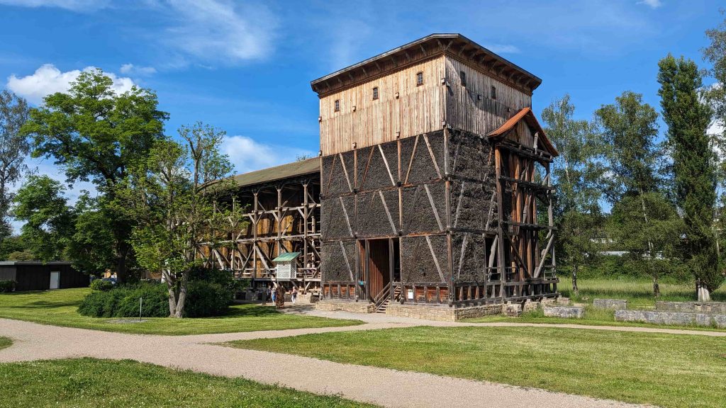
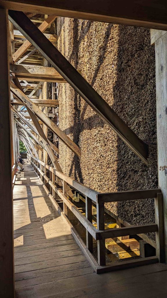
The graduation tower, the Gradierwerk, stands in the Luitpold Park and costs nothing to visit. A walkway along the Saale leads up to it. The town owes the structure to its old salt trade, and even now brine trickles down over walls of packed blackthorn brushwood on a great timber frame, throwing off a fine salt mist that is said to do the lungs good, something like the air off the North Sea. The thing that strikes you standing before it is that the whole of it is wood, a tall framework stuffed with thorn, far bigger than you expect. On an earlier visit we sat on the west side with the afternoon sun warm on our backs and the water cooling the air in front of us, breathing that clean salted air, and I came away genuinely persuaded that regular use of it would ease the breathing. I have two photographs I mean to keep with this: one of the whole timber structure in the sun (above), and one from the walkway inside (below), the brine-darkened thorn close at hand and the water running in its channel below. It is the inside shot that carries it.
The KissSalis Therme took us the better part of a half day. It is a large modern wellness complex, ten pools of various sizes inside and out across some eight thousand square metres, with nine saunas and steam baths besides. The big indoor and outdoor pools are made for families. There are treatment rooms you simply walk into, no booking, where you sit among strangers. Of the several kinds I remember only one clearly, so I will speak only of that: a saline mist room, an indoor and more concentrated cousin of the graduation tower. It was cool and thick with mist, the walls and floor finished in small mosaic tiles, with seats built into the walls, room for about a dozen at most. We stayed a quarter of an hour. On leaving you spray down the spot where you sat for whoever comes next, which is a civilised arrangement. The saunas sit within the textile-free section. Massages are easy to come by, and Ochi and I had a couples one, a head-to-toe thing lying side by side, which was as restful as anything we did all trip. One warning to pass on plainly: do not eat there, or if you must, go in with low hopes. We took dinner at the Therme and it was poor, a cheap set menu and dear for what it was.
Botenlauben Castle is the ruin we had meant to walk to today. It was the home of Otto von Botenlauben, a minnesinger and crusader, and his wife Beatrix de Courtenay. Otto was a songwriter of some standing, one of those gathered into the Codex Manesse, which I find a strange and pleasing thing to stand near. He sold the castle to the bishopric of Würzburg in 1234, and after that it passed through hands, fell into ruin, and was eventually quarried for its stone, so little is left. Two towers still stand, and you can climb both for a fine view over the town. There is a car park just beneath it for anyone who cannot manage the climb; on foot from the centre it is thirty to forty minutes, and a steep thirty to forty at that. Worth the effort even as a ruin.
The woodland walks wrap around that side of the town. They are beautiful and quiet and kept scrupulously clean. The tracks are compacted earth, the fire-road sort, with steps cut in where the slope steepens. What I remember is the smell: the resin of the spruce, and under it the damp leaf-litter, sweetish with a cool earthy note beneath, the kind the rain brings up. Birdsong the whole way round. It is as complete a disconnection from city and suburb as I know.
As for the town itself, it has been a UNESCO World Heritage Site since 2021, one of the Great Spa Towns of Europe alongside Bath, Vichy and Baden-Baden among others. Some twenty-two or twenty-three thousand people live here, in Lower Franconia, south-east of the Rhön, a little over two hundred metres up. It is more than twelve hundred years old, first written down around the year 801, with its long history first of salt and later of the mineral-water cures that drew kings and famous names. The Kurgarten dates to 1738 and is reckoned the oldest spa garden of its kind. What I keep coming back to, with the eye of a man presently doing up his own house and garden to sell, is how clean it all is, the houses and gardens kept with a care that shows. It quietly shames the effort I have been putting in at home.
We drove back and stopped at the local Netto for the journey, and that gave the real surprise of the day. A basket of the ordinary things we would buy at home came to just over forty-four euros. The same shop at our Sainsbury’s would be near sixty pounds, half as dear again, and the German quality every bit as good or better. Large jars of pickled gherkins were one ninety-nine, with all manner of other pickled things going cheaply too. It is the sort of thing that lodges in the mind once you are thinking, as we increasingly are, about how to provision the travelling years ahead.
A quiet day, then, taken slow on purpose, and none the worse for the rain.
A day with nothing in it that had to be done, which after the long drive and the longer day on the show ground was the whole point of it. Dry and warm, the sky changing its mind every half hour between flat grey and a clean, washed blue. We did not stir early.
In the late morning we walked out into the parkland, the same ground we had looked down on from the room on the first evening, when no photograph would hold the green. From inside it the green held itself perfectly well. We took about three quarters of an hour over it, an amble rather than a walk, along the gravel paths that thread between the tall spruce and out across the broad lawn, the wooded hills beyond the meadow closing the view in. We did not get as far as the spa quarter, nor did I much want to; the parkland was enough. Bad Bocklet is a spa town, which is what the ‘Bad’ in the name announces before you arrive, a small Bavarian market place of a few thousand people that has held the right to call itself a Markt since long before any of this was here. None of that pressed on the walk. It was simply a quiet town being quiet around us.
The one piece of practical business was the car. On the way out two days ago, at the first stop, I had noticed the headlight and indicator lens on the SL280 sitting loose in its housing, not falling out but no longer properly held, and I did not want it working itself free somewhere on the autobahn on the way home. So a short trip to a supermarket on the edge of town, a Netto, in search of tape. They had parcel tape and nothing else of any use to me. No duct tape, which is the thing one actually wants for a job like this. I bought the parcel tape and made do.
Back at the hotel I taped the lens, a stopgap and no more, enough to hold it steady for the run home. It is the sort of repair that looks worse than it is and works better than it looks. I will get the lens off properly once we are home, see whether a clip has gone or the lug has simply tired with age, and either fix it or replace it. The whole small episode left a clear note for the future: there should be a roll of duct tape in the van’s kit before we set off for the travelling years, not bought in a panic at a Netto in a strange town. An old vehicle wants steady small attention, and the things to put it right with ought to be aboard before they are wanted. The SL now, the Sprinter later, the principle is the same.
Dinner again at a quarter to seven, half board, and this time I wrote the wines down, having let the previous evening’s recommendations slip away unrecorded, which had nagged at me. Both were poured by the glass, the small two-tenths measure. The first was a Jubiläums-Cuvée, a dry white from Weingut Max Müller I at Volkach, classed as a Gutswein, the card promising yellow stone fruit and green apple, juicy, with a lively run of acidity, and delivering more or less what it promised, at seven euros fifty. The second was a Dürkheimer Feuerberg, a Blauer Portugieser, off-dry, from Weinkellerei Langenbach at Trier, ripe-fruited and full with a soft touch of residual sweetness, at seven euros even. No vintage shown on either, which I noticed and let pass.
The detail that rewarded a second look came afterwards, turning the two names over. The white is a Franconian wine, Volkach lying in Franken, which is as near to a local bottle as the week affords; the red, sold to us in the same breath as a local recommendation, comes by way of a Pfalz house at Trier, which is to say from somewhere else entirely. A ‘local’ wine that turns out to be half from another region is the kind of small slippage I would once have let go by. It grounds the glass in a place to know the difference, rather than leaving it as just a good white and a pleasant red.
Talk over dinner went back, as it has every evening, to the show: the forty-eight-volt storage, the recirculating shower, the diesel heater, the rest of the list. Nothing settled, nothing decided. We were only turning it over, the way one worries a stone in a pocket without meaning to throw it.
Breakfast from eight, and a wide spread to choose from. The bacon was the surprise: cooked properly, crisp without a film of grease on the plate, which is rare when a kitchen is feeding a full dining room at once. I took the cooked breakfast, a couple of pastries afterwards and coffee. Ochi had the cooked breakfast with fresh fruit, and was offered hot almond milk for her coffee, a small courtesy that pleased her.
Ten minutes by road to Bad Kissingen. We arrived early enough to take a place on the hard standing, of which there are only about a hundred. After that, cars are sent onto the grass, and the recent showers had left it too soft for the old vehicle, so the early start earned its keep. The show occupies a nature reserve, and movement on and off the ground is tightly controlled for that reason. By my reckoning the event has grown a great deal in both exhibitors and visitors across the twenty-odd years it has run.
The queue for the event coaches was already fairly long when we joined it, but far better managed than in the previous two years, when it had been a scramble with no order to it. This time there was a proper queue. The first coach came after about a quarter of an hour and we boarded the fifth, a ten-minute ride to the gates. They opened at ten; we were through at a little after a quarter past. Most people begin at the gates and work inward, so that end was crowded, and we went straight across to the far side and worked back towards the exit. We spent some five hours on the ground.
The first stand of any interest belonged to a firm (camping-pioneers) specialising in roof-top tents and in-vehicle table mountings, neither of which we want. What caught my eye instead were their own folding camping chairs, light and strong and genuinely comfortable, and a set of bamboo folding stools and a table of the Qeedo make. I flagged both for later thought rather than purchase.
Then to the first of the day’s real targets (Clesana), a maker of toilets that seal waste into a high-barrier bag for disposal, with no water and no chemicals involved. The company comes out of medical hygiene and moved into travel only a couple of years ago, first with a built-in model and then, this January, with a portable version. We had seen the portable one briefly at the Caravan Salon in Düsseldorf last year and wanted longer with it. It suits us almost exactly: small, light, battery-powered, easily moved. They were not selling on the day. The distributor sits in Scotland, and we were told that a trader near the gates was stocking them.
Directly opposite stood a water-treatment specialist (Purion), and water treatment was one of the chief reasons for the trip. They offer flexible, hard-wearing components for keeping stored water clean and disinfected without chemicals: filter housings that take standard cartridge sizes obtainable anywhere in the world, together with a UV-C lamp and driver to cycle the tank. A strong candidate for the build, and one I left thinking well of.
The find of the day was not on my list at all. A maker of recirculating showers (Dauer Shower), which solves a problem I have turned over for a couple of years. In a small van lived in full time, every litre of water must be carried, and a litre weighs a kilogram and fills a ten-centimetre cube. That is real weight and real volume, both competing with everything else aboard, and a shower is among the worst offenders for getting through water. The obstacle to recycling shower water has always been soap, which is awkward to separate, so existing systems tend to be either large, heavy and power-hungry or else they eat filters, neither acceptable in a van this size. Their answer is a hybrid. You shower in circulation mode for as long as you like, the water kept hot and clean through an easy-clean, long-life filter and using only a couple of litres; then you switch off, soap up, and run a short burst in fresh-water mode straight to the grey tank, so there is no soap to extract from the recirculated water at all. The maker quotes around five litres and 0.15 kWh per shower; my own guess is six to ten, set against the much heavier draw of an ordinary shower. I will write to them once we are home.
Energy storage next. The living side of the vehicle has long been held back by voltage: the usual twelve volts demands thick, heavy cable for anything that draws hard, which is to say cooling, heating and cooking. I have wanted to move to forty-eight volts for some time, but the kit has been scarce and dear. An Australian (Egon) firm announced a forty-eight-volt architecture in prototype last year and brought the first version to general sale this month, so forty-eight-volt batteries are now the thing required. This stand (Liontron) had a fifty-amp-hour forty-eight-volt unit on show, about 2.5 kWh; four in parallel would give ample capacity at roughly a hundred kilograms. Worth taking further.
A heating make (Scheer) new to me, though my heating plan is more or less settled, showed a diesel hydronic heater that holds a blue flame even from cold start through careful control of the air-to-diesel mix, which gives a clean, soot-free burn (typically these types of devices run a yellow, inefficient flame until at full burn temperature). I need heat for the living quarters, both underfloor and blown, for hot water, and for pre-heating the engine in very cold places. This unit is larger and heavier than I had imagined, and it draws on both AC and DC, which adds complexity, but it interested me, and the person on the stand had genuine technical depth.
The mattress question took up a good while at the stand of an Austrian maker (Flexima) of made-to-measure beds for vehicles, handmade. I want a bed left permanently made up rather than rebuilt from the seating each night. A roof-drop bed would cost too much height in a van already tall, with its raised suspension and large off-road wheels, so the plan is a bed that folds in two and stands upright at the rear when not in use. The mattress therefore has to be relatively thin, light and foldable down the middle, yet still comfortable after years of use. I tried two of theirs and found both very comfortable. The foam carries internal plastic spring elements that can be adjusted to firm or soften different zones, which I had not seen before. I spoke with Chris Schoneman, their Benelux director, and came away expecting this to be our choice. I mean to post a CAD drawing of the internal layout in a later entry.
A British company trading (GN Espace) from Widford in Hertfordshire, with a long history of supplying the marine trade, showed induction hobs and multifunction sinks that looked very well made. Worth another conversation.
We returned to a maker of hanging chairs of the hammock kind (Mira Art), which appealed to Ochi last year. We tried them again and liked them again. I have a suspension solution in mind already, so the difficulty is the weight and stowage of the parts rather than the chairs themselves. A luxury, to be settled last if there is capacity to spare.
I spent time with Michael Iglhaut, whose firm (Iglhaut) converted our vehicle into the capable off-roader it is back in 2000. That connection matters for the future: access to their knowledge of the vehicle and to their own parts as things wear or break, so I am glad to be building the acquaintance.
By the exit stood the trader we had been told about, and he had the Clesana X1 portable toilet in stock. We bought it there and then, so the van now has its toilet, the one firm purchase of the day.
So the day’s reckoning: the toilet bought; the Austrian mattress now the likely answer for the folding rear bed. Carried forward as candidates or jobs to do are the water-treatment components, the forty-eight-volt storage to match the new architecture, the diesel heater for further investigation, the recirculating shower to be contacted from home, the British induction hob and sink for another conversation, the folding chairs and bamboo stools flagged, and the hanging chairs left to last on grounds of weight and stowage. I took no photographs as I was too focused on the exhibitors.
Coach back to the car, the short drive to Kunzmann’s, and a look round the hotel’s spa before dinner at a quarter to seven. The local wines the hotel recommended were very good, but I failed to note their names, which I regret; I shall record tomorrow evening’s recommendations so they at least appear in the next day’s pages.